Investigation on the bulging deformation of continuously cast wide-thick slab with numerical calculation method
-
摘要: 连铸过程中铸坯已凝固,坯壳在钢水静压力作用下发生鼓肚变形,影响浇铸过程顺行与铸坯质量。以宽厚板连铸坯为对象,采用数值计算方法定量研究了其在连铸过程三个典型铸流位置L1 (弯曲位置)、L2 (弧形段中间位置)、L3 (矫直位置)的鼓肚变形规律。由L1至L3,坯壳鼓肚变形及其导致的凝固前沿拉伸应变均不断增加。凝固前沿厚度方向拉伸应变εxx、拉坯方向拉伸应变εyy与宽度方向拉伸应变εzz呈集中分布趋势,三者分别加剧三角区裂纹、中间裂纹及角部裂纹风险。随着拉速由0.7 m/min增大至0.9 m/min,宽面坯壳鼓肚变形与εxx、εzz先增加后减小,而窄面坯壳鼓肚变形与εyy持续增大。Abstract: In continuous casting process, bulging deformation of the solidified shell occurs due to the ferrostatic pressure, which influences the smooth production and the internal quality of the continuously cast steel. In the present work, the continuously casting wide-thick slab was taken as the research object, and its bulging deformation at three typical strand positions L1(bending region), L2(middle of the bow region) and L3(straightening region) was quantitatively investigated with numerical calculation method. Bulging deformation of the solidified shell and the tensile strain distribution on the solidification front continuously increase from L1 to L3. The tensile strain along the slab thickness direction(εxx), along the casting direction(εyy) and along the slab width direction(εzz) present a characteristic of concentrated distribution and increase the risk of inducing triple-point cracks, midway cracks and internal corner cracks, respectively. With the casting speed increased from 0.7 m/min to 0.9 m/min, bulging deformation of the wide surface of the solidified shell and εxx, εzz firstly increase and then decrease, but the bulging deformation of the narrow surface of the solidified shell and εyy continuously increase.
-
Key words:
- continuously cast /
- wide-thick slab /
- bulging /
- internal cracks /
- numerical calculation
-
0. 引言
浇钢过程中,已凝固坯壳在钢水静压力作用下发生鼓肚变形,从而影响连铸过程顺行与铸坯质量。坯壳鼓肚变形将增大拉坯阻力,从而加剧铸辊等铸机设备磨损,增加滞坯风险[1- 2]。此外,坯壳鼓肚变形促使枝晶间残余钢液向铸坯心部汇聚流动,从而加剧中心偏析[3- 4],同时坯壳凝固前沿因鼓肚变形产生的鼓肚应变将加剧内裂纹风险[5-8]。
准确揭示坯壳鼓肚变形规律,是设计连铸机辊列结构,优化二冷配水及其它生产工艺,保障连铸过程顺行与提升铸坯质量的关键理论依据。鉴于此,一些研究者采用解析法[9-14]与有限元法[15-20]针对连铸过程坯壳鼓肚变形规律开展了广泛研究。在解析法方面,Yoshii等[9]研究了辊间距变化对坯壳鼓肚变形形貌的影响,以及拉速波动与相同辊间距的铸辊个数对坯壳非稳态鼓肚变形作用规律。Han等[10]基于应变分析模型,计算了浇铸全程坯壳凝固前沿鼓肚与其它机械变形引起的应变规律。韩培培等[11- 13]通过建立两辊间坯壳动态鼓肚数学模型,研究了带液心矫直过程及铸辊错位情况下板坯凝固前沿应变、应变速率等坯壳变形特征。徐荣军等[14]将坯壳视为一对边固支另一对边简支的平板,并考虑坯壳高温蠕变特性,推导确定了温度场及钢水静压力共同作用下坯壳的鼓肚变形挠度解。在有限元法方面,Lee等[15]考察了拉速变化过程坯壳鼓肚形貌随时间变化规律,指出拉坯方向坯壳厚度不均匀性是引发非稳态鼓肚变形的主要因素。Miki等[16- 17]进一步阐明拉坯方向坯壳厚度不均匀性对非稳态鼓肚变形作用机制。Ha等[18]揭示了不同拉速、辊间距、二冷水强度条件下,铸坯表面鼓肚变形及坯壳表面与凝固前沿位置拉坯方向的鼓肚应变规律。Bellet等[19- 20]采用全局非稳态法开发了连铸坯二维热/力耦合有限元模型,系统揭示了浇铸全程包含坯壳鼓肚变形在内的铸坯凝固传热及变形规律。
笔者以某钢厂宽厚板坯连铸机为研究对象,基于由二维凝固传热模型计算确定的铸坯温度场与坯壳形貌,建立了三维坯壳鼓肚变形有限元模型,定量揭示了铸机弯曲、弧形段中间及矫直三个典型铸流位置的坯壳鼓肚变形及其导致的坯壳凝固前沿鼓肚应变规律,并对比分析了拉速对坯壳上述鼓肚变形规律的影响。
1. 三维鼓肚模型
1.1 建模参数
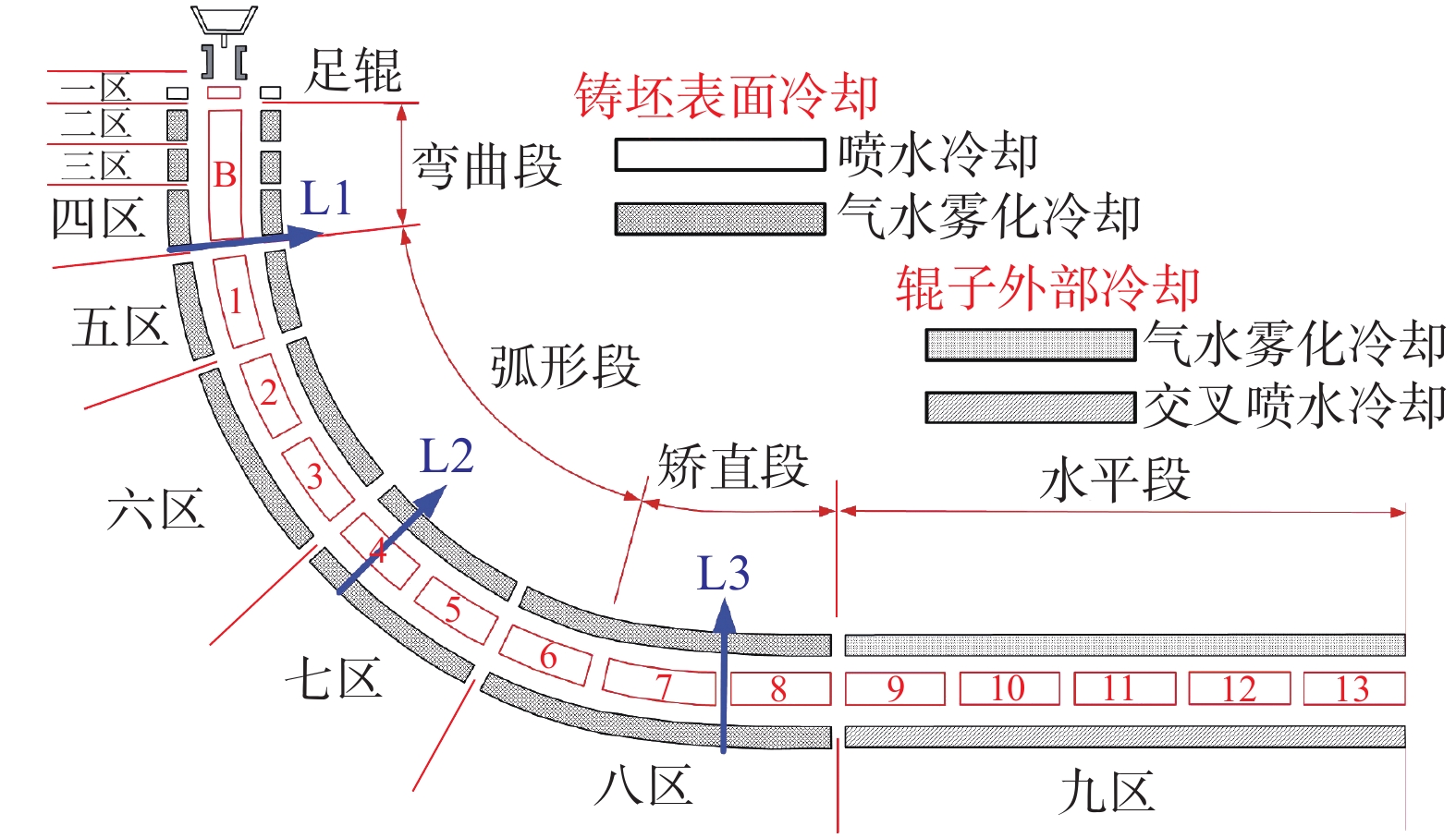
图1为所研究宽厚板坯连铸机结构,其包含14个扇形段(1个弯曲段,8个弧形段与5个水平段),可划分为9个二冷分区,具体冷却区参数如表1所示。
表 1 冷却分区参数Table 1. Parameters of the cooling zones in caster冷却分区 起始铸流位置/m 结束铸流位置/m 结晶器 0 0.80 二冷1区 0.80 1.04 二冷2区 1.04 1.60 二冷3区 1.60 2.71 二冷4区 2.71 4.26 二冷5区 4.26 6.18 二冷6区 6.18 10.02 二冷7区 10.02 13.86 二冷8区 13.86 20.49 二冷9区 20.49 30.33 以上述宽厚板连铸机生产的断面为2 000 mm×280 mm的Q345E (成分如表2所示)板坯为对象,定量研究了如图1所示三个典型铸流位置(L1、L2、L3)的宽厚板坯坯壳鼓肚变形规律。其中,L1位于弯曲位置,L2位于弧形段中间位置,L3位于矫直位置。
表 2 Q345E主要化学成分Table 2. The main chemical compositions of the Q345E %C Si Mn P S 0.17 0.31 1.5 0.014 0.011 1.2 有限元模型
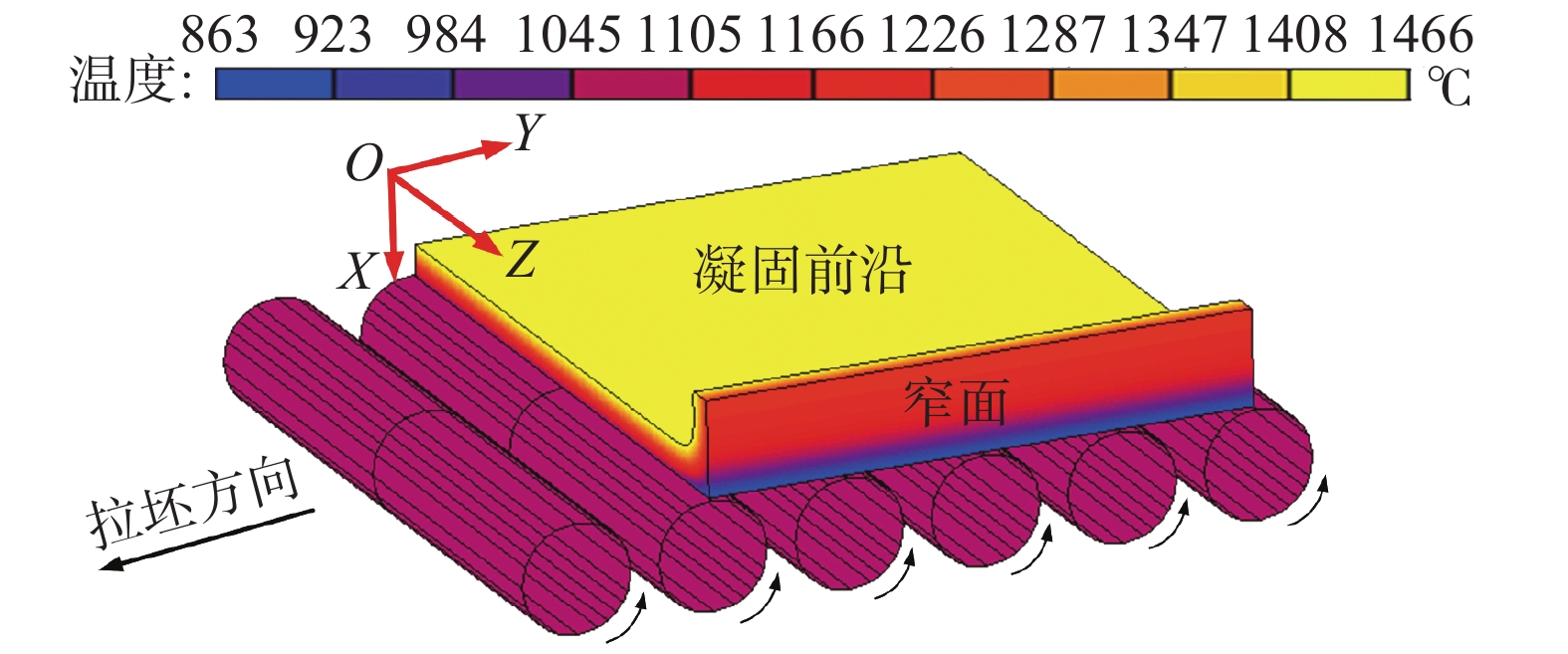
铸坯鼓肚变形与坯壳形貌及温度场分布密切相关。鉴于此,首先基于二维凝固传热模型计算了浇铸过程铸坯凝固传热规律,确定其在三个典型铸流位置(L1~L3)的坯壳形貌与坯壳温度场分布,二维凝固传热模型建模方法可参见作者相关文章[21- 22]。基于L1~L3三个位置处坯壳形貌及温度场分布,建立了如图2所示坯壳三维鼓肚变形模型。建模时,忽略铸辊变形,将其视为刚体,坯壳为可变形体。铸辊绕其轴心旋转,带动坯壳向前运动,铸辊转动速度为设定的拉坯速度。
浇铸过程中,坯壳温度较高,其变形过程蠕变特征明显。鉴于此,采用Kozlowski等[23]提出的弹性-黏塑性本构方程表征坯壳鼓肚变形过程:
$${\dot \varepsilon _{\rm{p}}} = C\exp \left( {\frac{{ - Q}}{T}} \right){\left[ {\sigma - {a_{\rm{\varepsilon }}}\varepsilon _{\rm{p}}^{{n_{\rm{\varepsilon }}}}} \right]^n}$$ (1) 式中,T为温度,K;C为与钢的成分碳含量相关系数,C=46 550+71 400 (wC)+12 000 (wC)2,MPa−ns−m−1;Q=44 650,为激活能常量,K;aε=130.5–5.128×10⁻³T,表示与温度相关常量,MPa s−nε;nε=−0.628 9+1.114×10⁻³ T,表示与温度相关的非弹性应变指数;n=8.132–1.540×10⁻³T,表示与温度相关的净应力指数;σ为应力,MPa;εp为非弹性应变。
建模时,弹性模量[24]与泊松比[25]采用如下公式计算确定:
$$E(T) = 968 - 2.33T + 1.9 \times {10^{ - 3}} \times {T^2} - 5.18 \times {10^{ - 7}}{T^3}$$ (2) $$\upsilon = 8.23 \times {10^{{\rm{ - }}5}}T + 0.278$$ (3) 式中,E为弹性模量,GPa;
$\upsilon$ 为泊松比;T为温度,℃。1.3 模型验证
一些学者[10- 11, 17]基于梁模型或平板理论,推导出两铸辊间坯壳最大鼓肚变形计算公式:
$${\delta _{{\rm{max}}}} = \frac{{P{l^4}}}{{3\;200{E_{\rm{e}}}{S^3}}}\sqrt t $$ (4) $${\delta _{{\rm{max}}}} = \frac{{P{l^4}}}{{3\;200E{S^3}}}\left( {1 + \sqrt t } \right)$$ (5) $$\begin{split} {\delta _{{\rm{max}}}} =& \left( {1/16} \right){\rm{ \times }}\left( {P{l^2}/E{S^3}} \right){\rm{ \times }}\\ &\left\{ {\left( {12/2} \right) - 3\upsilon {S^2} + \upsilon {{\left( {b + S} \right)}^2}} \right\} \end{split}$$ (6) 式中,δmax为坯壳最大鼓肚变形量,cm;P为钢水静压力,kg/cm2;l为辊间距,cm;t为坯壳经历一个辊间距所需时间,min;E及Ee分别为弹性模量及等效弹性模量,kg/cm2;S为坯壳厚度,cm;b为板坯宽度,cm;
$\upsilon $ 为泊松比。为验证模型准确性,采用公式(4)~(6)计算了L1~L3位置的坯壳最大鼓肚变形,并与有限元模型计算结果进行了对比,如表3所示。可以看到,有限元模型计算结果与公式(4)~(6)计算值范围符合较好,说明所开发有限元模型可比较准确地计算坯壳鼓肚变形规律。
表 3 坯壳最大鼓肚变形量公式计算值与模型计算值对比Table 3. Comparison of the maximum bulging deflection calculated by the FE model and the formulas位置 辊径/mm 坯壳厚度/mm 钢水静压力/MPa 最大坯壳鼓肚变形量计算值/mm 公式(4) 公式(5) 公式(6) 有限元模型 1 200 46 0.313 0.05 0.01 0.72 0.02 2 280 80 0.791 0.10 0.03 0.68 0.12 3 360 110 1.065 0.15 0.04 0.56 0.44 2. 计算结果与分析
2.1 坯壳鼓肚变形
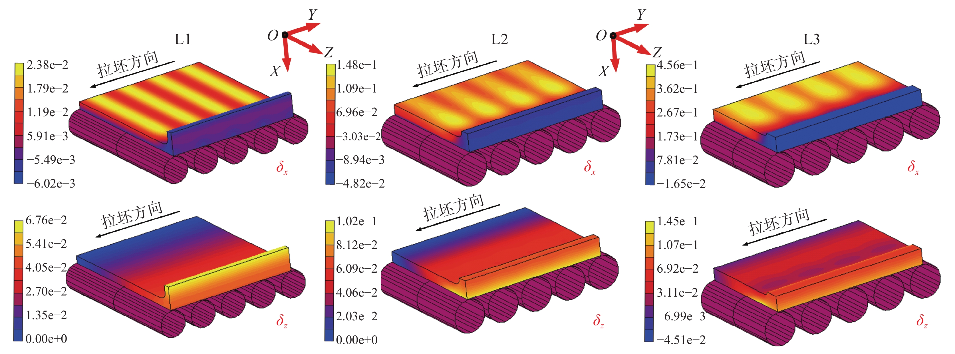
三个铸流位置处的坯壳鼓肚变形如图3所示。坯壳受钢水静压力作用,其沿宽度方向与厚度方向均发生明显鼓肚变形。由于坯壳宽面在两辊间无法得到铸辊的有效支撑约束,其沿厚度方向发生较大鼓肚变形(δx),且最大鼓肚变形位于两铸辊中间位置附近。窄面坯壳在浇铸过程无铸辊支撑,其沿宽度方向发生明显鼓肚变形(δz)。
三个铸流位置处,宽面坯壳宽度中心及窄面坯壳厚度中心位置在相邻两铸辊间的鼓肚变形分别如图4(a)、(b)所示。由于辊间距不同,4(a)、(b)采用了无量纲的辊间距(即两辊间位置与两辊间距比值)比较三个位置的坯壳鼓肚变形规律。从L1到L3,坯壳厚度将不断增加(如表3所示),对应的抵抗变形能力相应增强,但同时钢水静压力与辊间距也在不断增大。在二者综合作用下,如图4(a)所示宽面坯壳鼓肚变形(δx)不断增大。此外,由于高温坯壳变形过程具有明显蠕变特征,δx最大值并未发生于两辊中间位置,而是沿拉坯方向偏移一定距离。
窄面坯壳沿宽度方向的鼓肚变形(δz)如图4(b)所示。L1位置处,坯壳窄面沿铸坯宽向的鼓肚变形由厚度中心向角部位置方向呈现不断减小趋势。然而,随着窄面坯壳的不断增厚,L2及L3处窄面坯壳鼓肚变形的变化趋势与位置L1处正好相反。此外,随着L1至L3钢水静压力增加,铸坯窄面鼓肚相应增大。
2.2 凝固前沿鼓肚应变
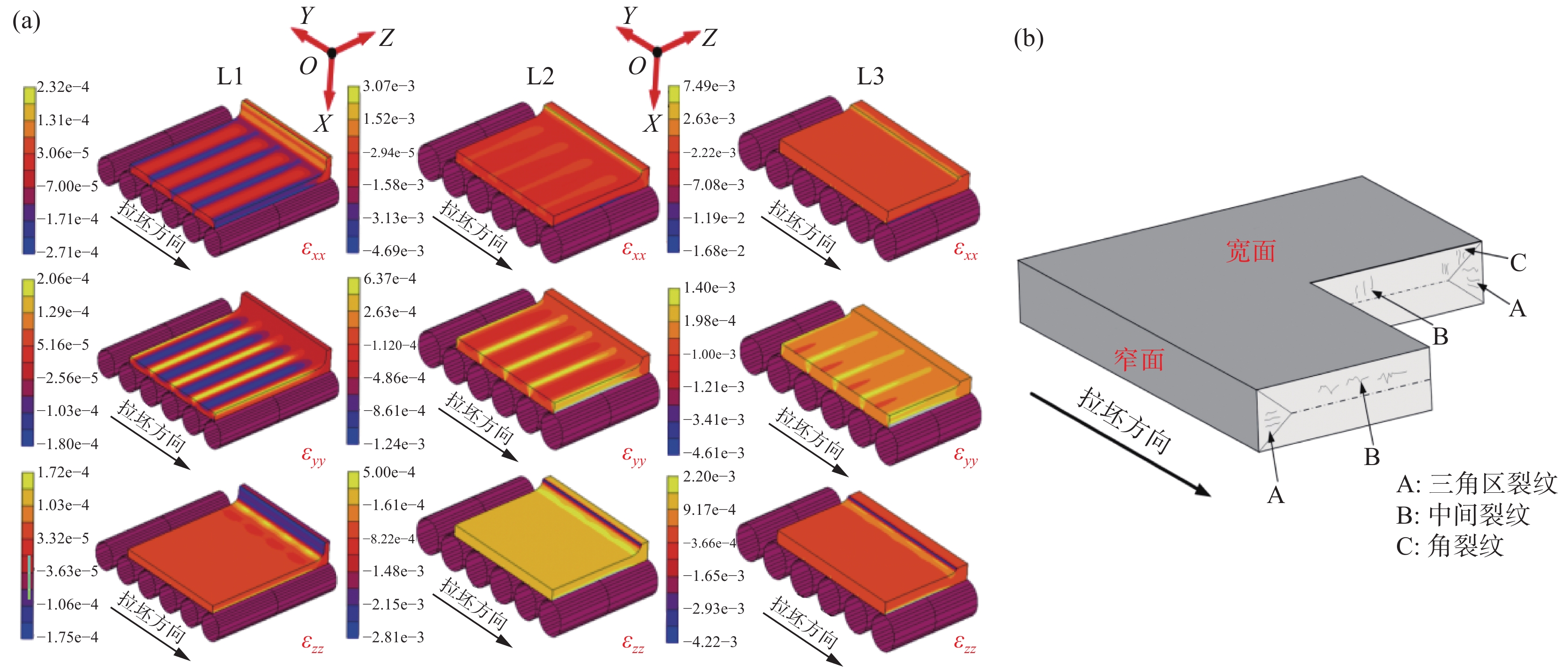
L1~L3坯壳凝固前沿厚度方向应变(εxx)、宽度方向应变(εzz)及拉坯方向应变(εyy)如图5(a)所示。在鼓肚变形作用下,坯壳同时产生了拉伸状态(应变数值大于0)及压缩状态(应变数值小于0)的应变,且最大拉伸应变在坯壳凝固前沿集中分布趋势。浇铸过程中,当坯壳凝固前沿位置由鼓肚变形及其它机械变形过程(如弯曲、铸辊错位、矫直等)引发的拉伸应变超过一定临界值时,极易在坯壳凝固前沿位置诱发内裂纹缺陷。因此,上述由坯壳鼓肚变形引发的凝固前沿位置集中分布的拉伸应变将明显增大铸坯相应位置发生内裂纹风险。
图5(b)为板坯常见内裂纹发生位置。对比图5(a)与图5(b)可知,坯壳凝固前沿拉伸应变εxx、εyy、εzz集中分布位置分别对应铸坯的三角区、支承辊上方及近铸坯角部区域。说明坯壳鼓肚变形导致的凝固前沿集中分布拉伸应变εxx、εyy、εzz将分别加剧铸坯三角区裂纹、中间裂纹及角部裂纹风险。
为定量阐明浇钢过程凝固前沿集中分布的拉伸应变演变规律,提取了如图6(a)所示位置的集中拉伸应变εxx、εyy、εzz,结果如图6(b)所示。由图6(b)可知,L1位置处钢水静压力及辊间距较小,该位置εxx、εyy及εzz基本相等。随着钢水静压力及辊间距不断增大,εxx、εyy及εzz均不断增大,且εxx增加速度明显高于εyy及εzz。在L2及L3处,εxx成为主导性的拉伸应变,其明显高于εyy及εzz。因此,在L2及L3处,由坯壳鼓肚变形引发三角区内裂纹风险最大。
2.3 拉速对坯壳鼓肚变形影响
随着拉速增加,铸坯在各冷却区内的有效冷却时间减少,坯壳整体温度升高,坯壳厚度减小,将不利用抑制坯壳鼓肚变形。然而,随着拉速增加,坯壳穿过两辊间距离所需时间(即坯壳蠕变变形)减少,从而倾向于减小坯壳鼓肚变形。
在上述两方面因素综合作用下,如图7(a)所示,当拉速由0.7 m/min增大至0.8 m/min时,宽面坯壳的最大鼓肚变形量呈现增加趋势,由0.105 mm增加至0.117 mm。随后,当拉速进一步由0.8 m/min增大至0.9 m/min时,宽面坯壳的最大鼓肚变形量则呈现出降低趋势,由0.117 mm减小至0.108 mm。不同拉速时坯壳窄面的鼓肚变形如图7(b)所示,可以看出窄面坯壳的鼓肚变形随拉速增大呈持续增加趋势。这说明,相比于坯壳在相邻两铸辊间的蠕变变形时间,坯壳厚度减小及其整体温度场增加对窄面坯壳的鼓肚变形影响更为显著。
图7(c)为不同拉速时图6所示位置处的拉伸应变。拉速由0.7 m/min增大至0.9 m/min,厚度方向拉伸应变εxx与宽度方向拉伸应变εzz呈现先增加后减小的变化趋势,两者在0.8 m/min时达到最大值。因此,拉速0.8 m/min条件下由坯壳鼓肚变形引发三角区裂纹及内角裂纹的风险性较高。此外,随着拉速由0.7 m/min增大至0.9 m/min,拉坯方向拉伸应变εyy由0.04%不断增大至0.06%。因此,随着拉速增加,由坯壳鼓肚变形引发中间裂纹的风险将不断增加。
3. 结论
1) 由L1(弯曲位置)至L3(矫直位置),宽面坯壳与窄面坯壳鼓肚变形不断增加,弧形段中间位置(L2)和矫直位置(L3),窄面坯壳的鼓肚变形由窄面中心向角部位置方向呈递增趋势,与L1(弯曲位置)的变化趋势正好相反。
2) 凝固前沿位置由鼓肚变形引起的厚度方向拉伸应变εxx、拉坯方向拉伸应变εyy及宽度方向拉伸应变εzz呈集中分布规律,三者分别加剧了板坯三角区裂纹、中间裂纹及角部裂纹风险。集中拉伸应变εxx、εyy与εzz由L1(弯曲位置)至L3(矫直位置)不断增大,其中,εxx从L2 (弧形段中间位置)开始成为主导性的拉伸应变,明显高于εxx及εyy,表明鼓肚变形引发三角区裂纹的风险明显高于引发中间裂纹及三角区裂纹风险。
3) 随着拉速由0.7 m/min增加至0.9 m/min,宽面坯壳鼓肚变形量及凝固前沿集中拉伸应变εxx、εzz呈现出先增加后减小的变化趋势,但窄面坯壳鼓肚变形量及εyy持续增大。
-
表 1 冷却分区参数
Table 1. Parameters of the cooling zones in caster
冷却分区 起始铸流位置/m 结束铸流位置/m 结晶器 0 0.80 二冷1区 0.80 1.04 二冷2区 1.04 1.60 二冷3区 1.60 2.71 二冷4区 2.71 4.26 二冷5区 4.26 6.18 二冷6区 6.18 10.02 二冷7区 10.02 13.86 二冷8区 13.86 20.49 二冷9区 20.49 30.33 表 2 Q345E主要化学成分
Table 2. The main chemical compositions of the Q345E %
C Si Mn P S 0.17 0.31 1.5 0.014 0.011 表 3 坯壳最大鼓肚变形量公式计算值与模型计算值对比
Table 3. Comparison of the maximum bulging deflection calculated by the FE model and the formulas
位置 辊径/mm 坯壳厚度/mm 钢水静压力/MPa 最大坯壳鼓肚变形量计算值/mm 公式(4) 公式(5) 公式(6) 有限元模型 1 200 46 0.313 0.05 0.01 0.72 0.02 2 280 80 0.791 0.10 0.03 0.68 0.12 3 360 110 1.065 0.15 0.04 0.56 0.44 -
[1] Ma Ruijin, Zhen Xingang. Especially thick slab continuous casting quality defects and the control defects and the control[J]. Continuous Casting, 2011,(S1):67−75. (马瑞金, 甄新刚. 特厚板坯连铸质量缺陷及控制[J]. 连铸, 2011,(S1):67−75. [2] He Yuming, Hu Bing, Liang Qing, et al. Development of key technology of generous slab crack control[J]. Continuous Casting, 2015,40(5):45−48. (何宇明, 胡兵, 梁庆, 等. 连铸宽厚板坯裂纹控制关键技术的开发[J]. 连铸, 2015,40(5):45−48. [3] Miyazawa K, Schwerdtfeger K. Macrosegregation in continuously cast steel slabs: preliminary theoretical investigation on the effect of steady state bulging[J]. Steel Research International, 1981,52(11):415−422. [4] Kajatani T, Drezet J M, Rappaz M. Numerical simulation of deformation-induced segregation in continuous casting of steel[J]. Metallurgical and Materials Transactions A, 2001,32(6):1479−1491. doi: 10.1007/s11661-001-0236-1 [5] Brimacombe J K, Hawbolt E B, Weinberg F. Formation of off-corner internal cracks in continuously-cast billets[J]. The Canadian Journal of Metallurgy and Materials Science, 1980, 19(2): 215−227. [6] Li Y J, Li H, Lan P, et al. Thermo-elasto-visco-plastic finite element analysis on formation and propagation of off-corner subsurface cracks in bloom continuous casting[J]. Journal of Iron and Steel Research International, 2017,(11):91−100. [7] Chen W, Zhang Y Z, Zhang C J, et al. Numerical simulation of the thermo-mechanical process for beam blank continuous casting[J]. Acta Metallurgica Sinica (English Letters), 2007,20(4):241−250. doi: 10.1016/S1006-7191(07)60034-9 [8] Zhu G S, Wang X H, Yu H X, et al. Formation mechanism of internal cracks in continuously cast slab[J]. Journal of University of Science and Technology Beijing, 2004,11(5):398−402. [9] Yoshii A, Kihara S. Analysis of bulging in continuously cast slabs by bending theory of continuous beam[J]. Transactions of the Iron and Steel Institute of Japan, 1986,26(10):891−894. doi: 10.2355/isijinternational1966.26.891 [10] Han Z Q, Cai K K, Liu B C. Prediction and analysis on formation of internal cracks in continuously cast slabs by mathematical models[J]. ISIJ International, 2001,41(12):1473−1480. doi: 10.2355/isijinternational.41.1473 [11] Sheng Yiping, Sun Jiquan, Zhang Min. Calculation for bulging deformation of continuously casted slab[J]. Iron and Steel, 1993,28(3):20−25. (盛义平, 孙蓟泉, 章敏. 连铸板坯鼓肚变形量的计算[J]. 钢铁, 1993,28(3):20−25. [12] Han Peipei, Ren Tingzhi. Influence of bulging of solidified shell on slab deformation in straightening zone of continuous casters[J]. Iron and Steel, 2016,51(4):24−30. (韩培培, 任廷志. 坯壳鼓肚对铸机矫直区内铸坯变形的影响[J]. 钢铁, 2016,51(4):24−30. [13] Han Peipei, Ren Tingzhi, Jin Xin. Influence of roll misalignment on bulging of continuous casting slab[J]. Iron and Steel, 2016,51(6):53−58. (韩培培, 任廷志, 金昕. 辊子错位对铸坯鼓肚变形的影响[J]. 钢铁, 2016,51(6):53−58. [14] Xun Rongjun. Behavior analysis of bulging deformation in slab casting process[J]. Heavy Mechanics, 2012,(1):17−21. (徐荣军. 板坯连铸鼓肚变形行为分析[J]. 重型机械, 2012,(1):17−21. doi: 10.3969/j.issn.1001-196X.2012.01.006 [15] Lee J D, Yim C H. The mechanism of unsteady bulging and its analysis with the finite element method for continuously cast steel[J]. ISIJ International, 2000,40(8):765−770. doi: 10.2355/isijinternational.40.765 [16] Ohno H, Miki Y, Nishizawa Y. Generation mechanism of unsteady bulging in continuous casting-1-Development of method for measurement of unsteady bulging in continuous casting[J]. ISIJ International, 2016,56(10):1758−1763. doi: 10.2355/isijinternational.ISIJINT-2016-172 [17] Toishi K, Miki Y. Generation mechanism of unsteady bulging in continuous casting-2-FEM simulation for generation mechanism of unsteady bulging[J]. ISIJ International, 2016,56(10):1764−1769. doi: 10.2355/isijinternational.ISIJINT-2016-171 [18] Ha J S, Cho J R, Lee B Y, et al. Numerical analysis of secondary cooling and bulging in the continuous casting of slabs[J]. Journal of Materials Processing Technology, 2001,113(1−3):257−261. doi: 10.1016/S0924-0136(01)00654-9 [19] Bellet M, Heinrich A. A two-dimensional finite element thermomechanical approach to a global stress-strain analysis of steel continuous casting[J]. ISIJ International, 2004,44(10):1686−1695. doi: 10.2355/isijinternational.44.1686 [20] Triolet N, Bobadilla M, Bellet M, et al. A thermomechanical modelling of continuous casting to master steel slabs internal soundness and surface quality[J]. Revue de Métallurgie–International Journal of Metallurgy, 2005,102(5):343−353. [21] Wu C H, Ji C, Zhu M Y. Analysis of the thermal contraction of wide-thick continuously cast slab and the weighted average method to design a roll gap[J]. Steel Research International, 2017:1600514. [22] Wu C H, Ji C, Zhu M Y. Deformation behavior of internal porosity in continuous casting wide-thick slab during heavy reduction[J]. Metals, 2019,9(2):128. doi: 10.3390/met9020128 [23] Kozlowski P F, Thomas B G, Azzi J A, et al. Simple constitutive equations for steel at high temperature[J]. Metallurgical Transactions A, 1992,23(3):903−918. doi: 10.1007/BF02675567 [24] Mizukami H, Murakami K, Miyashita Y. Mechanical properties of continuously cast steels at high temperatures[J]. Tetsu-to-Hagane, 1977,63(146):652. [25] Uehara M, Samarasekera I V, Brimacombe J K. Mathematical modeling of unbending of continuously cast steel slabs[J]. Ironmaking and Steelmaking, 1986,13(3):138−153. 期刊类型引用(3)
1. 何育民,罗阳,何博. 连铸板坯凝固过程的鼓肚应变分析. 钢铁钒钛. 2024(02): 125-131+161 .  本站查看
本站查看2. 钱志友,汪德富. 特厚板坯窄边鼓肚原因分析与控制. 河北冶金. 2023(10): 67-71 .  百度学术
百度学术3. 吴晨辉,李阳,谢鑫,吴国荣,曾建华. 板坯连铸过程凝固传热数值计算与工艺优化. 中国冶金. 2022(03): 92-98+125 .  百度学术
百度学术其他类型引用(3)
-


 下载:
下载:


 下载:
下载:


 百度学术
百度学术


